

A while ago, my Zendure 4-port charger that was running my home-server managed to cook itself to death, I quickly pressed my Anker PowerPort III 65W charger into service. But this left me short of a charger, so it was time to buy another.
Thanks to … you guessed it … OzBargain, I managed to pick up a charger that seemed somewhat well reputed amongst the crowd – a Novoo RG68. This was a 67W charger with two USB-C and one USB-A port and can be found on Amazon AU on sale for about AU$25 give-or-take. This one even promised a USB-C to USB-C cable, but not all of them do. At least this was not a HeyMix product, which enjoys quite the opposite reputation of getting slightly too toasty …
But is it any good? I’ve been (figuratively) burned by some cheaper chargers not being able to deliver their power ratings for long periods, so let’s put this one to the test.
Unboxing

This package has been sitting in the review queue for a while. Aside from the slight twitch I get when seeing the model number RG68 not match with the 67W rating, the package is relatively clean and simple, sporting a grey and orange colour scheme and featuring the product on the front. The charger is a “brick” in a cute and compact kind of way – the packaging indicates GaN components with over-temperature protection.

The rear provides the full specifications – 67W maximum on a single port, or various combinations having 45+18W, or 40+10+10W all ports laden, with USB-C port 1 being the favoured port. The product indicates a weight of just 99g, which is both light and slightly concerning, considering the power rating. Nevertheless, there is a badge that says “Certified Safe”, but by whom, I have no idea. This particular package with the cable carries the model number NCAU67D-257H.

A logo adorns the sides.

The underside has the approval logos which include the Australian RCM, making it compliant for sale in Australia. The manufacturer is Wellmade Corporation Limited, a Hong Kong-based company.

The package has a cardboard insert which holds the charger in place. A small leaflet and a service card is included.

The charger in its glory – a simple two tone grey and matte black – thankfully not the soft-touch plastic that will turn gooey. It’s a chalky-feeling matte black. The Australian plug is not interchangeable – instead, it’s solidly connected which is nice. The body of the charger is roughly the same footprint – so it won’t block adjacent outlets, but it is a bit “longer” than initially expected. The left side has the Novoo logo.

The right side has the GaN marking and 67W power rating.
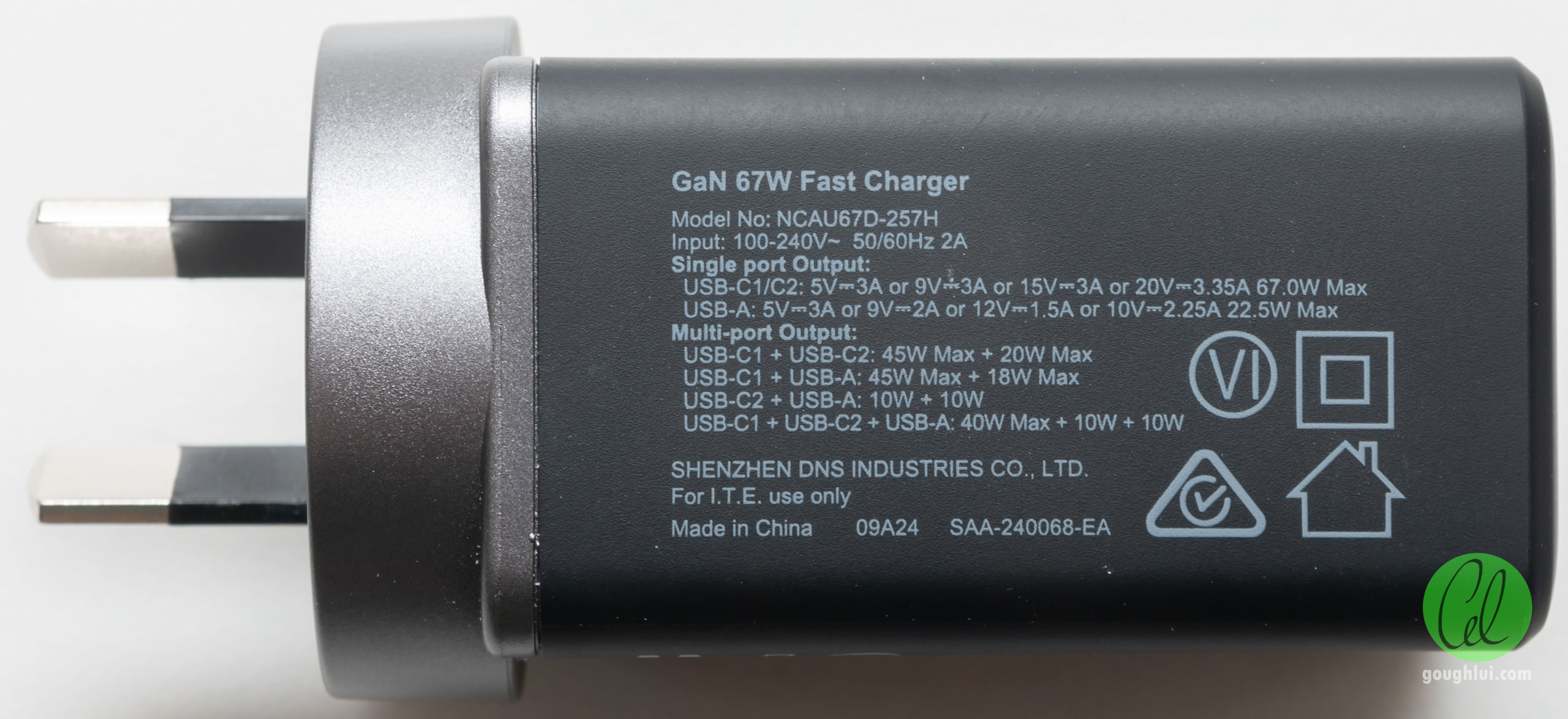
The full specifications are underneath, and it seems the true manufacturer is Shenzhen DNS Industries Co. Ltd. It has an efficiency mark of VI and an SAA number of SAA-240068-EA dated 23rd January 2024.
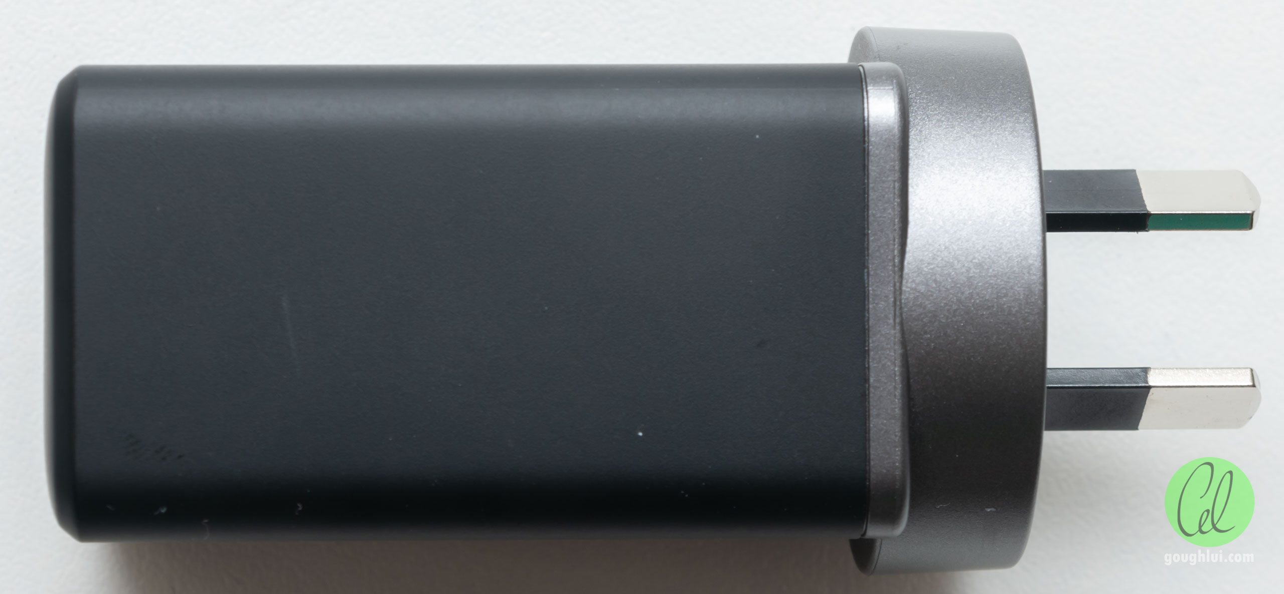
The top surface is clean and the plug has sleeved pins, as is required by code.


The USB-C primary port is on top, with the secondary port underneath and the USB-A port on the bottom. The USB-C ports have a black tongue, while the USB-A port has a purple tongue (which is quite unique).

The included USB-C to USB-C cable has metal plug bodies and a braided line, but the cable itself is quite stiff. It holds its shape, not liking to straighten out easily. I wonder if this is because it’s not as stranded as other cables, or perhaps it’s using stiff insulation or shielding. The cable diameter itself is a bit on the small side too – but considering it’s a “bundle-in”, that’s still a nice touch.


This was a package ordered later in a follow-up deal, as I needed another. Gone is the colour image of the product, replaced by a line-art image instead, and also gone is the USB-C to USB-C cable. I suspect this was a slightly different listing, but based on the model number being the same (NCAU67D-257H), you will find it hard to tell.

Surprisingly, this one’s also slightly less environmentally friendly, having a plastic tray inside. The charger itself is the same though.

Here is the charger and cable compared to the Dell 65W adapter that came with the Latitude 5420 – the smaller size and weight really makes a difference to my backpack and this is a combination that works just the same (albeit, a bit less cable with the Novoo solution). Of course, the Dell adapter isn’t likely optimising for size – but more for cost and longevity.
Performance Tests
This section contains the result of several tests I ran on my unit.
Weight

When it comes to weight, the charger weighs in at just slightly less than the claimed weight – 98.18g based on my scales. This is quite light …
Fast Charging Modes


Both USB-C ports when tested one at a time provide the above results when tested with a Fnirsi FNB58. The result shows the USB-C PD advertising five PDOs – four fixed (5/9/15/20V@3A) and one PPS (3.3-11V@5A). The majority of fast charge modes are detected as supported, with the exception of VOOC-based modes and QC5.0.

The USB-A port similarly has great legacy fast charging mode support.
Efficiency
Testing was performed with a Tektronix PA1000 Power Analyser and a B&K Precision Model 8600 DC Electronic Load and YZX Studio USB-C decoy board.
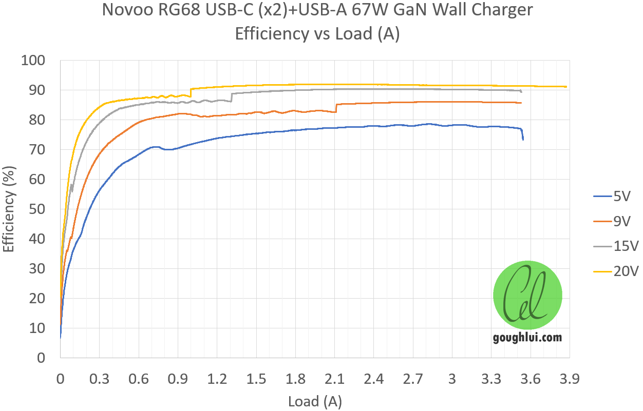
As a GaN charger with a VI efficiency mark, I was expecting good efficiency results and the test showed somewhat mixed results.

At 5V which is relatively low loading overall, the charger efficiency struggled to reach 79%. Only at higher loads did it really shine. At 20V, the peak efficiency was about 92%. Interestingly, this is actually less than the 93% achieved by the non-GaN Anker PowerPort III – but that’s likely because of a difference in design topology and could be down to measurement errors (1-2% would not be unexpected). There is a penalty to power-sharing multi-port designs too. As for the jump in efficiency curve – I suspect that may be a change of operating mode or measurement shunt.

Plotted versus load power, the jump in the efficiency curve seems to line up at around the 20W mark.

The same data, zoomed in. The “hook” at the end of the curve shows what happens when the adapter hits over-current protection and folds back its voltage, resulting in a power reduction. These curves go from (near) zero load to OCP at all voltages.
Output I-V Curves

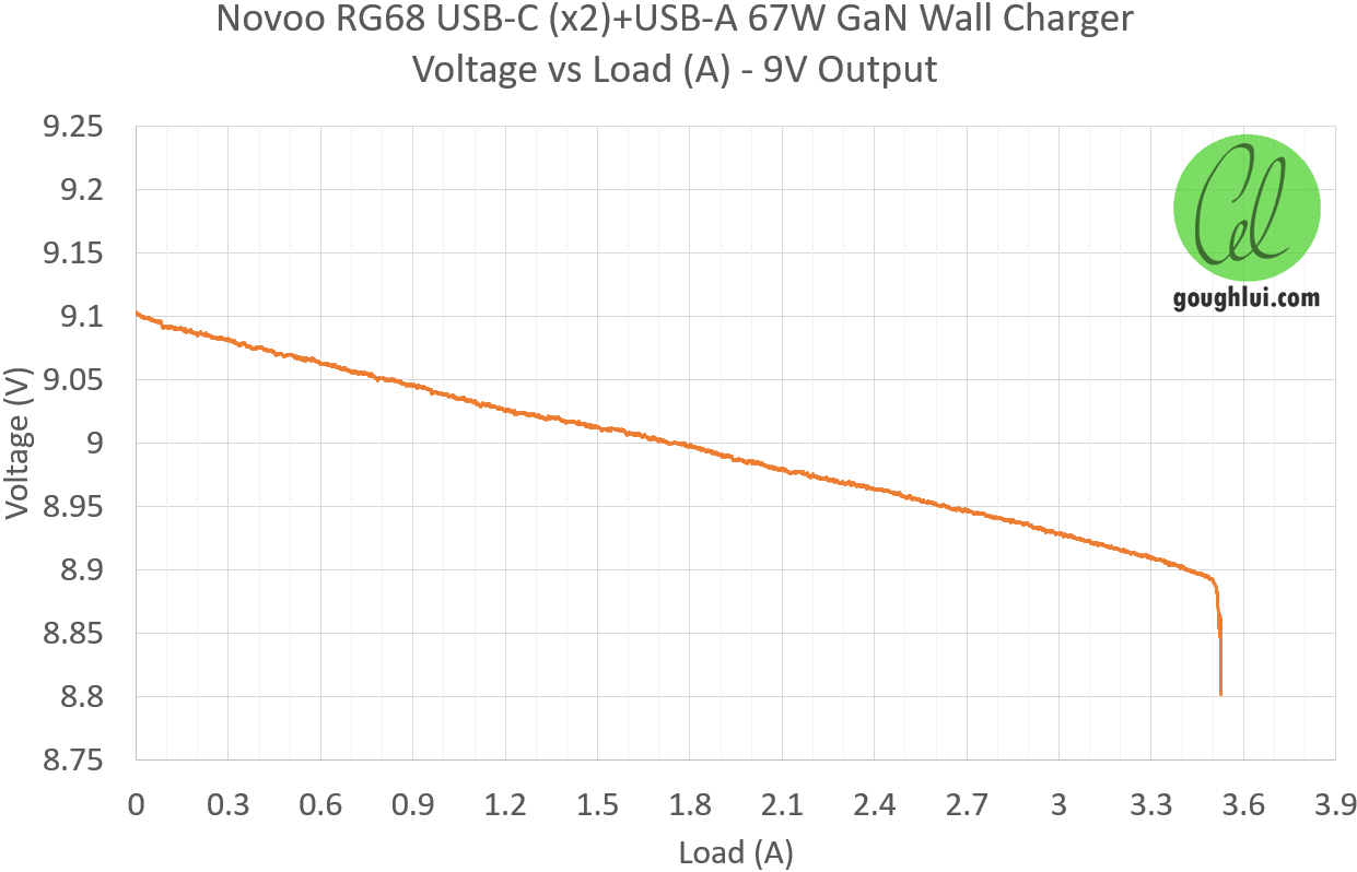


Using the above data, I saw that the output I-V curve started slightly above the target voltage (but safely so) and declining smoothly and ohmically until hitting OCP when it falls off. There may be a negative-impedance linear cable compensation, but maybe not, and the ohmic characteristic is due to the short length of cable used in testing.
Load Endurance

Can it stand the test of time? Yes. Two hours of 67W load and it’s still showing a steady power input, as well as the requested 20V/3.35A, in a fairly cool (~20 degrees C) and still ambient environment.
Thermals


Under sustained load, I took thermal images of the RG68 using a Topdon TS001 thermal camera. It shows that the heat seemed fairly evenly distributed across three of the four sides with the surface reaching a slightly toasty 62 degrees Celsius. You wouldn’t want to be in contact with that for too long …
Ripple and Noise
Unfortunately, I wasn’t able to get quality ripple and noise measurements consistent with previous measurements due to a change of measuring hardware needed for USB-C connections. As a result, I’m using the Rohde & Schwarz MXO4 oscilloscope with the Rohde & Schwarz NGM202 Power Supply and a YZX Studio USB-C decoy board. The NGM202 means sink current is limited to 3A (so 60W maximum) and the decoy board has some internal capacitors which serves to reduce the measured ripple.

When unloaded, the unit goes into a power saving discontinuous operation state. The ripple is about 71mV peak-to-peak.


At all voltages at 3A load, the ripple ranged from 25mV to 39mV peak-to-peak which seems quite good – but some of this may be due to the smoothing effect of the decoy board’s capacitances. In all, I didn’t see anything particularly bad here.
Standby Power

The standby power as measured to IEC62301 protocol using PWRVIEW was 280.98mW with an uncertainty of 18mW. This is quite acceptable.
Insulation Resistance


Using a Keysight U1461A insulation resistance test multimeter, all three ports measured >260Gohms at 1000V DC to the mains side, indicating good isolation between primary and secondary (at least, when new).
Teardown
As they’re not too expensive and now I have more than one in my hands, let’s take one apart.

A bit of “persuasion” is all that’s needed to separate the plug from the body. The seam is siliconed into place and surprisingly, they haven’t used a sliding pin contact like some other chargers have – instead opting for a more manual wiring set-up with silicone insulating the back of the pins. The charger PCB is siliconed into the shell too, to keep it in place. A bit of work with a knife and pliers was necessary to free the board from the shell.

The assembly is quite complex but it is wrapped around its entirety by a band of aluminium plate which serves as a heatsink, itself covered along some edges by insulating tape.

Below the folded aluminium plate, there is a piece of insulation that is likely thermally enhanced. The plate also serves as shielding, as it is soldered to the PCB in the bottom-right of the image.

Elsewhere, it is held in place with copious amounts of thermal silicone adhesive. We can see the primary bulk capacitance is parallel sets of ordinary aluminium electrolytic capacitors from Acon rated 18uF 400V. I don’t believe these capacitors are reputed for reliability – they’re likely more middle-low grade stuff which is a bit disappointing.

More insulating tape and cut-outs in the heatsink sheet to accommodate the mess of boards that is inside this “sandwich”. It seems this is never designed to be taken apart.

From the USB plug end – count them – that’s four PCBs. Three vertical pieces and one main along the bottom. The two USB-C PCBs also have a wire heading from one to the other. A tight squeeze – there is a solid aluminium electrolytic, but also a regular one below it seems. The tightness of the fit is impressive, but also potentially scary especially if those clearances ever get violated – perhaps this is why there’s so much silicone just to make sure those boards don’t move.
Now, I had to get a little destructive, desoldering the drain tab and breaking the silicone goop attachment to the heatsink. After this, I might still be able to reassemble it, but the heat dissipation capability will be compromised, so the charger may not handle its full power rating anymore.

Nevertheless, with such a design, boards sticking through other boards, it seems they’ve opted to use solder fillets to join the boards. While the fillets seem rather chunky, I suppose one should still be careful with plugging things in to avoid over-stressing the joints in the long run.
The PCB itself seems to have a date code of Week 33 of 2024, making this fairly new. Looking closer, on the primary side, there is a big chip marked FMRGPA. I have no idea who is behind it, but my best guess is that this is the “GaN” part of the solution and it’s some form of all-in-one AC to DC buck controller with integrated FET and feedback.
The reason I say this is because the other transistors that can be seen (Wayon 50N03L4 and CJAB 35N03S) are regular silicon trench n-MOSFETs.

From the side, the primary input is fused through a time-delay 5A fuse which is quite a large fuse – perhaps the inrush is big on this adapter, but that is a fuse that could let a lot of power get through in an adverse event. Nevertheless, this board seems to host an optocoupler for feedback, one Y-capacitor in a chip-shape with an empty spot above it.

One of the port controllers can be seen too – a Zhuhai iSmartWare SW3516P.

From the top, the transformer is marked with 255H BSY (manufacturer?) 2425 (date code). Four primary filter capacitors can be seen, one hiding behind a safety X2 capacitor – all Acon. A toroidal inductor is seen partly near the goo, for the USB-C 1 primary port.

Not much to see from the other side – the transformer just having its heat transferred to the aluminium plate with more grey silicone. The USB-A port mezzanine board is marked AC-255H-C-V0.2 dated 7th November 2023. I suppose AC-255H-C is the internal product name.

More digging through the silicone goop seems to suggest a second SW3516P is used for the secondary USB-C port and the USB-A port, as a single controller can handle one port of each. Then they’ve somehow linked the two SW3516P together to do some power sharing arrangement.
This suggests the topology uses a GaN controller to produce an intermediate DC voltage and that is then bucked by the SW3516P and supporting silicon MOSFETs and inductors to the required voltage. The double-conversion definitely adds an efficiency cost and two controllers also adds a quiescent power cost too.
Conclusion
It’s amazing how cheaply USB-C PD chargers of the 60W class can be purchased for nowadays. But as I’ve long suspected, many of the cheaper chargers which advertise their GaN nature rarely offer much improved performance over good competent silicon-only designs. In this case, it seems more like a hybrid GaN + silicon design, where GaN is likely only used in the first AC-to-DC intermediate voltage stage, with silicon handling the buck conversion from there.
Nevertheless, this charger is lightweight (sub-100g), compact (around the size of the plug, just longer), has a sturdy fixed Australian plug, does manage excellent legacy fast charging mode compatibility, has stable output voltage and sustains a 67W output indefinitely while having its exterior heat up to about 62 degrees Celsius. Ripple (based on decoy-board usage) seems stable and quite good too. Insulation resistance passed with flying colours.
Efficiency was good at high loads, peaking at about 92%, but using it at light 5V loads saw efficiency struggle to hit 79%. The standby power of 280.98mW is quite acceptable, but perhaps not class-leading.
Internally, it was a very tight design with little free space and lots of silicone holding things in place. The construction comprises four PCBs, three of them standing off the main board, joined at their bases with solder fillets, wrapped around by an aluminium plate acting as a heatsink and shield. In all, it looks okay, but perhaps that time-delay 5A primary fuse looks a bit big for my liking and those Acon primary side capacitor and one regular electrolytic in the secondary are a bit of an unknown when it comes to longevity.
We can’t expect too much, given its price, and so far it seems to work just as intended with lots of features to like. I certainly was happy enough to get a couple more units. Let’s see how long it lasts in service … I suppose that depends on how they are used too …
For 5W power it’s maybe better to use smaller charger. My similar Novoo 100W charger also seems to be 70% efficient for 5W, although other testers seems to report a bit more. Maybe it’s my measurement errors.